Earthmoving Techniques: Grade, Cut, Fill, and Mass Haul Explained
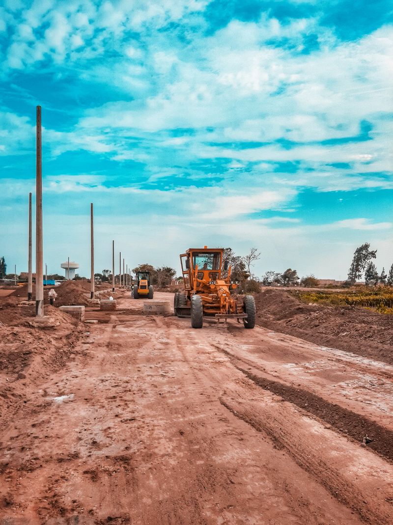
Earthmoving is simultaneously one of the most straightforward and most technically demanding aspects of construction. At its core, you’re moving dirt from where it is to where it needs to be. In practice, executing that efficiently — on grade, on schedule, within budget — requires a solid understanding of site plans, material behavior, equipment capabilities, and sequencing.
This guide covers the fundamentals every earthmoving professional should know: reading grading plans, understanding cut and fill, dozer and scraper techniques, compaction requirements, and how GPS-assisted grading workflows have changed the game.
Reading Site Plans and Grading Drawings
Before a blade hits the ground, someone needs to interpret the grading plan. Grading drawings (also called grading plans or earthwork plans) show:
- Existing contours — usually shown as dashed lines, representing the current ground surface
- Proposed contours — shown as solid lines, representing the finished grade
- Spot elevations — specific elevation points at key locations (building corners, drainage inlets, parking lot corners, road centerlines)
- Slopes — indicated as ratios (2:1 means 2 feet of horizontal run for every 1 foot of vertical rise) or percentages (2% grade)
- Drainage arrows — showing intended water flow direction
The first step is always understanding the datum and benchmark — the reference elevation from which all others are measured. On most civil projects, this is tied to NAVD88 (North American Vertical Datum of 1988), though some older projects or private sites use local benchmarks.
Key Terms on Grading Plans
- Finish Grade (FG) — the final graded surface elevation
- Subgrade — the compacted earthen surface below pavement, floor slabs, or base course
- Top of Curb (TC) — a common reference for parking lot and road grading
- Flow Line (FL) — the bottom elevation of a ditch or pipe
- Percent Grade — rise over run, expressed as a percentage (1% = 1 foot of rise per 100 feet of run)
Understanding these plan details before starting work prevents costly mistakes. Spend time reviewing the plans in the office, asking questions, and walking the site to correlate what’s on paper with what’s in the field.
Understanding Cut and Fill
Cut refers to areas where existing ground is above the design grade — material must be removed. Fill refers to areas where existing ground is below design grade — material must be added. The goal in good site design is to balance the earthwork — the volume of cut material equals the volume needed for fill, minimizing material import or export.
Why Cut-Fill Balance Matters
Importing fill material (buying dirt from an outside source) costs money — hauling, material cost, and placement time. Exporting cut material (hauling excess dirt off-site) costs money too — trucking, dump fees, and time. A well-designed site minimizes both by matching cut volumes to fill needs.
Earthwork takeoffs calculate these volumes from grading plans using methods like the Average End Area method or grid-based calculations. Project engineers provide cut/fill summaries; earthmoving contractors should review these carefully and verify against field conditions.
Shrink and Swell
Materials don’t maintain their volume as they’re excavated and compacted:
- Swell — soil expands when excavated (loosened). A cubic yard of soil in the ground (bank measure) becomes 1.10–1.30 cubic yards when loaded in a truck (loose measure).
- Shrinkage — compacted fill takes up less volume than the bank material used. Compaction factors vary by soil type; clay typically shrinks more than sand.
Ignoring shrink/swell in earthwork estimates leads to significant miscalculations. A 10% swell factor error on a 10,000 cubic yard job means you’re hauling 1,000 extra cubic yards you didn’t plan for.
Grade Stakes and Laser Levels
Before GPS became mainstream, grade stakes were the primary communication tool between surveyors and operators.
Reading Grade Stakes
A typical grade stake has two parts:
- The hub — a wooden stake driven flush with the design subgrade elevation (the operator grades to the top of the hub)
- The guard stake — a taller stake beside the hub with information written on it: cut/fill amount, station, offset, and sometimes material type
Reading a guard stake: “C 2.4” means cut 2.4 feet from existing ground to reach the hub elevation. “F 1.8” means fill 1.8 feet. The operator grades to make the ground level with the hub top.
Laser Levels for Grading
A rotating laser level broadcasts a flat or sloped reference plane across the site. A mast-mounted receiver on the grader or dozer picks up the laser signal and displays a cut/fill indication. Laser-based grade control is accurate, inexpensive (compared to GPS), and well-suited for parking lots, building pads, and other flatwork.
For sloped work, a dual-slope laser can establish a plane that slopes in two directions simultaneously — useful for crowned road sections or drainage-sloped pads.
Dozer Grading Techniques
The dozer is the primary earthmoving machine for rough grading and pushing material over short distances. Effective dozer operation is a skill that takes years to develop — but understanding the fundamentals accelerates the learning curve.
Rough Grade
Rough grade establishes the approximate shape of the site, getting within a few tenths of a foot of the design grade. The focus is on production — moving bulk material efficiently rather than achieving precision.
Key rough grade techniques:
- Slot dozing — pushing material in the same path repeatedly, building up a windrow on each side. The slot traps material at the blade, reducing spillage and increasing productivity. Effective for long pushes.
- Downhill dozing — whenever possible, push downhill. Gravity assists, fuel consumption drops, and cycle times improve.
- Blade loading — maintain a full blade with material to maximize each pass. An underfull blade is inefficient; an overfull blade creates excessive spillage.
- Avoid overpushing — pushing material past the fill area and then reworking it wastes time. Plan your push distances.
Finish Grade
Finish grade brings the surface to within specification tolerances — typically ±0.1 foot (1.2 inches) for subgrade work or tighter for paving prep. Finish grading requires:
- Lighter blade loads — less material on the blade for better control
- Slower speeds — more deliberate passes with careful elevation checking
- Cross-checking — cutting in multiple directions to remove high spots and fill low spots
- Feathering — gradually reducing blade depth as you approach grade to avoid overcutting
On smooth finish grade work, a rear ripper is often used to loosen the top 3–4 inches of material before final grading passes, allowing the blade to accurately cut and move small amounts.
Dozing Patterns
- Box cut — dozing a rectangular cut area, pushing material to one end. Efficient for excavating building pads.
- Side cast — pushing material to the side as you travel. Common for cut slopes and ditch work.
- Spreading — pushing fill material out across the fill area in thin, even lifts for compaction. Critical technique for fill construction.
Scraper Operations for Mass Haul
When earthwork volumes are large and push distances exceed 300–400 feet, scrapers become more economical than dozers and trucks. A scraper loads its own bowl, hauls material, and dumps/spreads it — combining three machine functions in one.
Types of Scrapers
- Push-pull (conventional) scrapers — require a push dozer to help load the bowl. Most common type.
- Self-loading (elevator) scrapers — have a loading elevator that fills the bowl without a push dozer. More expensive but eliminates the need for a dedicated push machine.
- Twin-engine scrapers — two engines for maximum pull-through on tough loading conditions.
Haul Road Management
Scraper productivity depends heavily on haul road conditions. Watered, graded haul roads reduce rolling resistance and tire wear dramatically. On large jobs, dedicated haul road maintenance (a small dozer or grader keeping roads smooth and watered) pays significant dividends in scraper production.
Cycle time drives scraper economics. A scraper cycling every 8 minutes produces twice the volume of one cycling every 16 minutes. Minimize haul distances, maintain roads, and sequence cuts and fills to keep haul distances short.
Compaction Requirements
Getting dirt to the right elevation is only half the battle — it also has to be compacted to specification. Compaction increases soil density by reducing void spaces between particles, improving load-bearing capacity and reducing future settlement.
Soil Types and Compaction
- Granular soils (sand, gravel) — compact well with vibration. Use vibratory rollers (smooth drum or pad foot). Achieve compaction quickly, drain well.
- Cohesive soils (clay, silt) — compact best with kneading action. Use pad foot (sheepsfoot) rollers or pneumatic tire rollers. More sensitive to moisture content.
- Mixed soils — most common in practice; require judgment on roller type and pass counts.
Moisture Content
Soil compacts best at or near its optimum moisture content (OMC) — the moisture level at which the maximum density is achieved. Too dry, and particles won’t bond; too wet, and water fills the voids instead of compacting out.
On the field, operators and superintendents use simple tests:
- Ball test — squeeze a handful of soil; it should hold its shape but crumble when dropped
- Penetration rod — a simple device that measures resistance
A proctor test (lab test from soil samples) establishes the OMC and maximum dry density for the specific soil on site.
Lift Thickness
Fill should be placed in controlled lifts — layers of specified thickness that can be uniformly compacted throughout. Standard lift thicknesses:
- Structural fill (building pads, below slabs): 6–8 inches loose, compacted to 95% standard proctor
- Roadway subgrade: 8–12 inches loose per lift
- Embankment fill: 12 inches loose per lift is typical; some specs allow more for granular materials
Thicker lifts save time but risk inadequate compaction in the middle of the lift. Never deviate from specified lift thicknesses on structural fills.
Compaction Testing
Most specifications require compaction testing by a geotechnical technician using a nuclear density gauge or sand cone test. Tests verify that the required density (often 95% of standard proctor, or 98% for heavy structural fills) is achieved before the next lift is placed.
Failing a compaction test means rework — additional roller passes or reworking the moisture content. Building compaction testing into the schedule avoids delays.
Drainage and Slope Considerations
Water is the enemy of earthwork. Poorly drained sites cause:
- Unstable subgrade under pavements
- Erosion of graded slopes
- Standing water that prevents access and operations
Design adequate drainage from the start:
- Minimum slopes — most paved surfaces require at least 1–2% slope for drainage; turf areas need at least 2%
- Temporary erosion controls — silt fences, inlet protection, straw wattles per your SWPPP (Stormwater Pollution Prevention Plan) during construction
- Interceptor ditches — divert uphill runoff around your work area
- Subgrade drainage — in high-water-table areas, underdrain systems may be required before fill placement
Slope stability is a separate but related concern. Cut slopes in stable soils are typically designed at 2:1 (H:V); softer soils may require flatter slopes. Fill slopes at 2:1 are common with good compaction; steeper fill slopes require engineering.
GPS-Assisted Grading Workflow
GPS machine control (covered in detail in our separate GPS grade control guide) has changed the earthmoving workflow significantly. The key operational differences:
- Design model prep — grading plan is converted to a 3D surface model in software (Trimble Business Center, Carlson, or equivalent) before work begins
- Base station setup — RTK base station establishes at a known survey point (or network RTK service activated)
- Machine calibration — blade tip positions calibrated relative to GNSS receivers
- Rough grade operation — operator works to on-screen cut/fill display without grade stakes; checker verifies periodically with a GPS rover
- Finish grade — automatic blade control engages; operator controls travel direction and speed
- As-built verification — GPS rover or drone survey verifies finished grade against design model
The efficiency gains are real: fewer stakes, fewer surveyors, fewer passes, less rework. For complex sites with multiple design elevations and slopes, GPS grading virtually eliminates the confusion and errors that arise from trying to hold multiple stake grades simultaneously.
Motor Grader Finish Work
The motor grader brings the final precision to earthmoving. After dozer rough grade and initial compaction, the motor grader makes finish passes to achieve tight tolerances for paving prep.
Motor grader finish grading technique:
- Multiple passes — typically 2–4 passes to progressively tighten grade
- Windrow management — material cut by the blade builds up in a windrow; periodically cast it to the shoulder or push it back to fill low spots
- Checking grade — in pre-GPS work, the operator checks with a string line or level rod regularly; with machine control, the screen provides continuous feedback
- Overlap — each blade pass overlaps the previous by 30–40% to avoid ridges
A skilled motor grader operator is one of the most valuable people on a civil site. The quality of the finish grade directly determines pavement thickness consistency, material usage, and long-term pavement performance.
Earthmoving is a discipline where small improvements in technique, planning, and sequencing compound into major differences in project outcomes. Master the fundamentals here and you’ll have the foundation to consistently deliver grades on time, within budget, and to spec.

Ironworks Insider Editorial Team
Independent trade-focused editorial team