Excavator Quick-Coupler Lock Verification Checklist
Quick answer
Every attachment change requires verification against the exact coupler and attachment instructions. Identify the hitch, follow its OEM engagement procedure, install or confirm the specified safety device, inspect the lock from a safe position, complete only the manufacturer-approved verification test, and keep everyone outside the drop and swing zones.
Common questions
- Is there one curl test that verifies every excavator quick coupler?
- No. Manual, semi-automatic, hydraulic, double-locking, pin-grabber, and dedicated couplers use different safety devices and verification procedures. Follow the exact manufacturer instructions.
- Can a ground worker stand near the bucket to confirm the lock?
- Only from the safe position and under the communication method defined by the site and manufacturer. No one should enter the attachment drop zone, swing radius, or another crush zone.
Source note: Reviewed against OSHA's quick-coupler safety bulletin and UK HSE quick-hitch guidance. The coupler, excavator, and attachment manuals control the engagement and verification procedure.
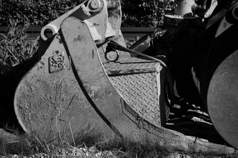
An excavator attachment can appear connected and still release without warning. That is why attachment changeover is not complete when the coupler control says “locked.” It is complete only after the operator has followed the specific coupler procedure, confirmed every safety device, and verified engagement from a safe position.
There is no universal curl, shake, or ground-pressure test that fits every hitch. Coupler geometry, control logic, retaining pins, locks, sensors, and approved verification methods differ. Use this checklist to organize the job, then perform only the steps in the manuals for the excavator, coupler, and attachment.
Why visual appearance is not enough
OSHA investigated multiple incidents in which excavator buckets unexpectedly released. Its quick-coupler safety bulletin describes a fatal incident involving a locking pin that had not been installed and notes that poor engagement and locking are common factors in unexpected releases.
The UK’s HSE quick-hitch guidance similarly highlights missing retaining pins or bars and calls for operator competence on the specific hitch, checks after every attachment change, and visual confirmation when the lock cannot be seen from the cab.
Those sources establish the hazard, not a universal procedure. Manufacturers have many different designs and retrofit requirements. If the identity or instructions are uncertain, tag the coupler out until the manufacturer or dealer confirms them.
Step 1: identify the exact hitch and attachment
Before moving the machine, record:
- Coupler manufacturer, model, serial number, and type
- Excavator model, serial number, and control configuration
- Attachment manufacturer, model, pin diameter, pin spacing, width, and weight
- Required safety or retaining pin, bar, wedge, hook, latch, or secondary lock
- Electrical or hydraulic connector requirements
- Rated use, including whether lifting with the coupler is permitted
Do not assume two buckets that fit between the ears are compatible. Pin centers, diameters, wear, hook geometry, and allowable combinations matter. Adapters or mixed-brand components require written compatibility information, not a trial fit.
Keep the current manuals in the cab or fleet document system. The attachment overview in our excavator attachments guide can help plan selection, but the manufacturer’s compatibility data controls.
Step 2: control the attachment-change area
Choose firm, level ground with enough room for the full attachment, stick, boom, and upper-structure movement. Place the attachment in its stable changeover position as instructed by the manufacturer.
Establish an exclusion zone that covers:
- The attachment’s possible fall, roll, or tip path
- The excavator’s swing radius and counterweight
- Pinch points between the coupler, attachment, and ground
- Hydraulic hose movement and any stored-energy zone
One trained operator should control the machine. If a spotter is required, agree on signals and stop-work authority before movement begins. The operator must stop when visual contact or communication is lost. No one should stand between the attachment and machine or beneath a raised attachment.
These controls should be part of the daily heavy-equipment pre-operation inspection, especially when several operators or attachments share one machine.
Step 3: inspect before engagement
With the machine and attachment placed safely, inspect the coupler and attachment interfaces for:
- Cracks, deformation, damaged welds, or unauthorized repairs
- Worn hooks, jaws, wedges, pins, bushes, or locking surfaces
- Dirt, ice, concrete, or debris that prevents full seating
- Missing retaining pin, clip, bar, spring, guard, or secondary device
- Hydraulic leaks, damaged hoses, loose fittings, or chafed wiring
- Damaged indicators, sensors, alarms, switches, or control labels
- Incorrect or improvised pins, bolts, wire, or retainers
Never replace a manufacturer-specified retaining device with a convenient bolt or scrap pin. HSE explicitly warns against improvised substitutes. Do not weld, grind, or modify a coupler without the manufacturer’s approved repair instructions.
Step 4: engage and lock by the exact OEM procedure
Follow the sequence for that coupler. Depending on the design, the procedure may involve cab controls, a manual safety pin, a powered primary lock, a secondary lock, a pressure requirement, or a defined attachment position.
The operator should be able to answer:
- Which attachment pin or feature must enter the coupler first?
- What confirms that both engagement points are fully seated?
- Which primary and secondary locking devices must move?
- Does a manual retaining device have to be installed?
- What does each indicator or alarm actually confirm?
- What abort or reset action does the manual require if engagement fails?
An indicator lamp may confirm a sensor state rather than prove that every mechanical surface is seated. Treat the display as one part of verification, not the only evidence.
Step 5: verify visually from a safe position
Lower and position the attachment as the manufacturer requires before anyone leaves the cab or approaches. Neutralize controls, apply the parking brake, and follow the machine’s shutdown or control-isolation procedure.
From the defined safe viewing point, confirm:
- The attachment pins or interfaces are seated in the intended hooks or jaws
- The primary lock is in its fully engaged position
- The secondary lock or safety device is engaged
- The correct retaining pin, bar, and clip are installed when required
- Indicator alignment marks show the expected condition
- No gap, debris, damage, or misalignment contradicts the locked indication
Use a flashlight, mirror, camera, or second trained observer only when the site procedure and manufacturer permit it. No closer look justifies entering a drop zone or placing a body part between components.
Step 6: perform only the approved physical test
Some manufacturers prescribe a specific controlled test after visual verification. The attachment position, direction of force, ground contact, engine speed, control movement, and acceptance criteria can vary.
Do not substitute a generic bucket curl, shake, slam, or lift test. The wrong movement can hide partial engagement, damage a safety device, destabilize the machine, or release the attachment. Keep the exclusion zone clear throughout the approved test, then recheck the visual and indicator evidence required by the manual.
Record the change when site rules require it: machine, coupler, attachment, operator, time, and verification completed. A simple log supports shift handoffs and helps supervisors audit the process.
Tag out any questionable coupler
Stop, lower the attachment safely, isolate the machine, and tag it out when:
- The coupler or attachment identity is unknown
- Compatibility cannot be confirmed
- A lock, retaining device, guard, indicator, or alarm is missing or damaged
- Pins, hooks, jaws, or locking surfaces exceed wear limits
- The coupler will not complete the prescribed engagement or test
- There is a crack, deformation, leak, or unauthorized modification
- The operator has not been trained on that exact system
Do not continue using the machine because the attachment “held last shift.” A partially engaged coupler can work temporarily and release later.
Include the coupler in training and maintenance
Training must cover the actual coupler models operators use, not only general excavator controls. Competency should include identification, compatibility, exclusion zones, engagement, visual checks, the approved physical test, fault response, and restrictions on lifting.
Maintenance records should track wear measurements, lubrication, fastener checks, hydraulic and electrical condition, safety-device function, applicable inspection intervals, and manufacturer updates or recalls. Add the coupler to the broader excavator maintenance schedule rather than treating it as an untracked accessory.
Verify lifting restrictions separately
A lifting eye does not automatically authorize every lifting operation. Confirm the coupler’s rated lifting points, load chart effects, attachment configuration, hook or eye inspection, rigging requirements, and applicable regulations. Some couplers or configurations restrict lifting; others require a dedicated lift point and specific load chart.
Plan lifts under the site lifting procedure and relevant heavy-equipment safety requirements. Never carry a suspended load over people, and never rely on the attachment-retention system as an undocumented lifting connection.
The decisive habit is straightforward: identify, isolate, engage, visually confirm, and complete only the OEM-approved test after every change. If any part of that chain is uncertain, the attachment stays grounded and the coupler stays out of service.

Ironworks Insider Editorial Team
Independent trade-focused editorial team