Hydraulic Cylinder Drift: Find the Cause Safely
Quick answer
Cylinder drift does not prove the piston seal has failed. Capture when and how the load moves, inspect for external leakage, compare the hydraulic schematic with the symptom, and have a qualified technician isolate the cylinder, directional valve, counterbalance valve, and related circuit safely.
Common questions
- Does hydraulic cylinder drift always mean bad piston seals?
- No. Internal leakage through a directional valve, counterbalance valve, pilot-operated check valve, or another connected circuit can produce similar movement. The circuit must be tested methodically.
- Can a worker check drift under a raised attachment?
- No. Never enter a crush zone or work beneath an attachment supported only by hydraulics. Lower the load or use the OEM-approved mechanical support and isolation procedure.
Source note: Reviewed against Parker mobile-cylinder application guidance and Bosch Rexroth load-holding valve discussion. OEM schematics, safe load support, pressure-release procedures, and technician test specifications control.
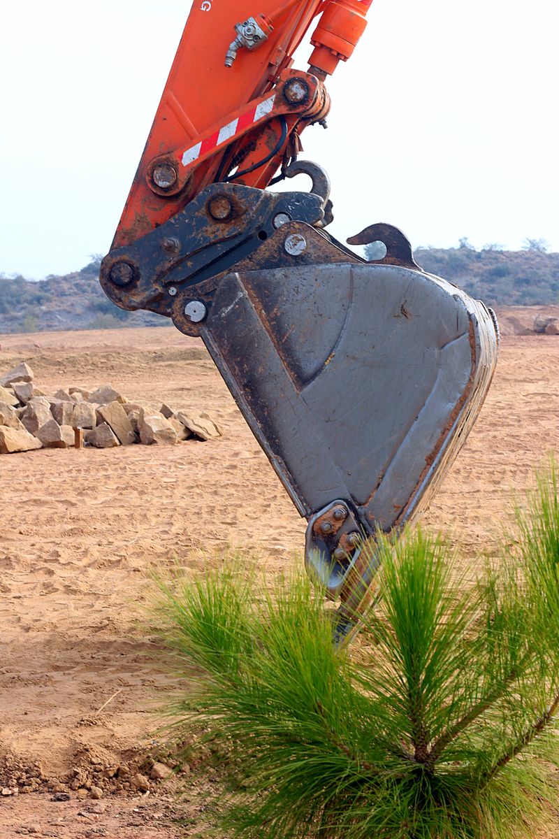
A boom, bucket, blade, or stabilizer that slowly moves with the controls centered is reporting a real fault. The difficult part is locating it. Hydraulic cylinder drift can come from piston-seal bypass, but it can also come from a directional valve, counterbalance valve, pilot-operated check valve, plumbing connection, or mechanical load path.
Replacing a cylinder based on the symptom alone can waste money and leave the hazard in place. A better approach captures the operating pattern, reads the circuit, and gives a qualified technician a safe, model-specific test plan.
Make the machine safe before observing drift
Never stand under or reach into the path of an attachment supported only by hydraulic pressure. A drifting load can accelerate, a hose can fail, and a control can be moved unexpectedly.
Before inspection or service:
- Park on the surface and in the configuration specified by the manufacturer
- Lower the attachment to the ground whenever possible
- Shut down, isolate energy, and release stored pressure by the OEM procedure
- Use only the manufacturer’s approved mechanical support when a component must be raised
- Establish a crush-zone exclusion area and control the keys
- Treat oil escaping under pressure as an injection hazard; never use a hand to find a leak
If safe support or isolation cannot be established, stop. The observation is not worth exposure to an unsupported load. These controls should already be part of the fleet’s hydraulic system maintenance program.
Capture the symptom before parts are disturbed
Drift rate alone does not tell the whole story. Record the conditions under which the movement occurs so a technician can reproduce it without guessing.
| Observation | Diagnostic value |
|---|---|
| Direction of movement | Narrows which cylinder chamber and load path are involved |
| Engine running or stopped | Helps separate supply/control effects from a static hold condition |
| Oil cold or at operating temperature | Internal clearances and oil viscosity change with temperature |
| Attachment empty or loaded | Load can expose leakage or mechanical movement not visible unloaded |
| Cylinder near retracted, mid-stroke, or extended | A damaged bore or seal may behave differently by position |
| Steady movement, step movement, or settling then stop | Suggests different leakage, trapped-air, geometry, or linkage patterns |
| One function or several functions | May point to a local component or a shared valve/supply issue |
Measure from a safe reference point outside the crush zone. Use time-stamped photos or a fixed indicator only if it can be installed with the attachment grounded and the system depressurized. Do not place a person where the moving component could pin them.
Also note ambient temperature, hydraulic oil temperature, recent repairs, fluid changes, fault codes, and unusual noise. The excavator maintenance schedule offers a useful framework for connecting the symptom to service history.
Rule out external leakage and mechanical movement
Inspect the machine with the load safely grounded. Look for wetness at the rod seal, barrel, ports, hoses, tubes, manifolds, and valve body. Check for a scored or bent rod, loose cylinder pins, worn bushings, cracked mounts, or linkage play that can look like hydraulic movement.
Clean suspect areas by the approved method, then observe from a safe distance during an authorized function check. Cardboard or another non-contact aid may help reveal a leak; hands do not. A suspected high-pressure injection injury requires emergency medical care even if the skin wound looks small.
External leakage is evidence, but its absence does not clear the circuit. Internal leakage leaves no puddle.
Read the hydraulic schematic as a load-holding map
Obtain the correct hydraulic diagram for the machine serial number and attachment configuration. Trace both cylinder ports back through every component that can connect them to tank, supply, or another actuator.
Pay particular attention to:
- Directional control valve: spool-to-bore clearance can permit internal leakage even in neutral
- Counterbalance or overcenter valve: contamination, incorrect adjustment, pilot problems, or seat damage can affect load control
- Pilot-operated check valve: a seat, poppet, or pilot circuit problem can prevent positive holding
- Port relief and makeup valves: faults can open an unintended path
- Load-sense and regeneration passages: some circuits intentionally interconnect flows during movement
- Hose-burst or load-control valves: configuration and test requirements vary by application
Bosch Rexroth’s actuator-drift discussion explains why clearance flow through a directional spool can allow movement and why a seated load-holding valve is used in some designs. That principle does not mean a particular machine should be modified or that its valve is automatically at fault.
Cylinder bypass is one possibility, not the default verdict
Worn or damaged piston seals can let oil pass between cylinder chambers. The result may be load creep, reduced force, heat, or movement that changes with temperature and stroke position. Barrel scoring, contamination, damaged wear bands, or an incorrect seal installation can contribute.
Parker’s mobile cylinder application guide notes both that seal bypass can permit drift and that apparent piston-seal leakage is not always traceable to the piston. Its catalog tests and limits apply to the described Parker products, not universally to every machine.
Do not copy a catalog’s pressure, leakage limit, or disconnected-line test into a field procedure. Cylinder design, area ratio, load-holding hardware, plumbing, contamination control, and safe blocking requirements differ. Opening the wrong pressurized line can release oil or cause uncontrolled movement.
Build a technician test plan
A qualified hydraulic technician should decide how to isolate the fault using the OEM service manual, schematic, rated test equipment, and approved supports. A useful work order asks the technician to:
- Confirm the reported drift under controlled, repeatable conditions
- Verify external and mechanical causes have been evaluated
- Record system temperature, load, position, pressures, and drift rate
- Identify every possible internal flow path on the schematic
- Isolate the cylinder from valve and circuit leakage by the OEM test method
- Test load-control and directional valves to their specified leakage and setting criteria
- Inspect fluid condition and contamination evidence before installing replacement parts
- Recheck the complete safety function after repair
Pressure gauges, flow meters, caps, plugs, and hose assemblies must be correctly rated and clean. The test plan must account for trapped pressure on both sides of a component. A generic internet method is not adequate authorization to disconnect a line.
Let the pattern guide the next question
Useful diagnostic questions include:
- Does drift worsen as the oil warms? Record the change without naming a failed component. If an excavator also shows a hydraulic-temperature warning or broader hot-only performance loss, use the excavator hydraulic oil overheating worksheet to capture the pattern and route the machine safely.
- Does it occur only under load? Check the load-holding design, pressure path, mechanical structure, and cylinder condition.
- Does only one cylinder drift? Focus on its local actuator and valve path while still checking shared passages.
- Do several functions creep? Investigate the common valve bank, pilot supply, return pressure, or control issue.
- Does movement change by stroke position? Consider barrel, seal, geometry, linkage, and hose-routing effects.
- Did the symptom start after contaminated oil or a component failure? Use oil analysis and filter inspection to protect any repair from a repeat failure.
These are routing questions, not proof. The safe conclusion comes from a controlled isolation test against manufacturer specifications.
Repair the cause and the conditions behind it
If a cylinder failed because contamination scored the barrel, replacing seals without addressing the oil and filters invites another failure. If a valve seat is damaged by debris, find the source. If an attachment settles because the wrong component was fitted, verify the serial-number parts application and configuration.
After repair, document the measured before-and-after condition, test all affected functions, inspect for leaks, and confirm that guards, supports, and safety devices are restored. The right outcome is not simply “the drift stopped.” It is a stable, specification-compliant circuit whose load-holding behavior has been verified without exposing anyone to stored energy or an unsupported attachment.

Ironworks Insider Editorial Team
Independent trade-focused editorial team