Hydraulic pump whining: What the sound can tell you
Quick answer
A hydraulic pump whine does not prove the pump has failed. Stop for warnings, leaks, heat, foamy fluid, debris, or changed machine response; otherwise document when the sound occurs, how it changes with temperature and engine speed, and which functions are affected. Safe external checks may reveal a fluid-level, filter-indicator, or visible damage clue, but inlet, pressure, flow, case-drain, control, and internal-wear testing belongs to a qualified technician following the exact OEM procedure.
Common questions
- Does a whining hydraulic pump mean it needs replacement?
- No. A new whine can accompany inlet restriction, aeration, unsuitable cold-start viscosity, loading or control behavior, coupling or mounting problems, or internal wear. Replacement should follow model-specific tests and measured evidence.
- Why does a hydraulic pump whine when the oil is cold?
- Cold oil may be more viscous and harder for the pump to draw through its inlet path, but the exact approved fluid, warm-up procedure, and acceptable sound are machine-specific. Persistent or worsening noise still needs investigation.
- Can air in hydraulic oil sound like cavitation?
- Yes. Danfoss notes that air in fluid can produce noise similar to cavitation. Foam or cloudy fluid can support an aeration branch, but the observation does not locate the entry point or prove the cause.
- What should an operator record for a hydraulic whine?
- Record the machine and pump identity, hour meter, exact warning or code, cold-versus-warm timing, engine speed, functions in use, load condition, response changes, fluid appearance, filter indication, recent service, and a safe audio or video sample.
Source note: Reviewed October 2026 against the Danfoss Series 90 pump service manual and hydraulic-fluid maintenance guidance, Caterpillar hydraulic-system inspection guidance, and OSHA hazardous-energy requirements. The exact machine, pump, and attachment manuals control fluid checks, warnings, isolation, test points, limits, and return-to-service decisions.
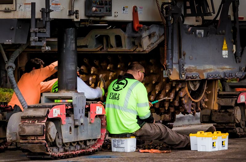
Hydraulic pump whining is a symptom, not proof that the pump has failed. A changed sound may follow an inlet restriction, air in the fluid, cold or unsuitable oil, a control or loading condition, loose or misaligned drive hardware, or internal wear. The useful question is not “Is the pump bad?” but “Exactly when does the sound appear, and what changes with it?”
Stop operating when the OEM warning or manual requires it, or when the new noise comes with a leak, sudden heat warning, foamy fluid, metal or other debris, smoke, damaged hardware, or slow, jerky, or unpredictable movement. Do not keep cycling the machine to make the symptom repeat.
Hydraulic pump noise diagnostic matrix
Use the matrix to preserve a pattern before service changes it. It routes the next check; it does not confirm a failed part.
| Noise character | Operating state | Temperature pattern | Companion symptom | Evidence path |
|---|---|---|---|---|
| High-pitched whine that follows engine speed | Idle and all functions | Cold and warm | No warning; response appears normal | Compare with the machine’s known baseline; document recent service, pump drive, and mounting history for an OEM-guided inspection |
| Rough whine, growl, or gravel-like sound | Startup or when demand begins | Strongest when cold | Slow initial response or filter indication | Check only the operator-approved fluid level and indicators; technician checks the inlet path, approved fluid, and measured inlet condition |
| Irregular whine or crackle | Idle or multiple functions | Any temperature | Foam, cloudy oil, or jerky response | Stop if response is unsafe; preserve photos and service history for an aeration investigation |
| Whine during one function | Boom, steering, travel, swing, or one attachment | Cold, warm, or both | Only that circuit is slow, pulses, or triggers a code | Record the exact function, direction, control input, load, mode, and attachment; technician follows that circuit’s schematic |
| Whine only with combined functions or load | Two functions together or higher demand | Often clearer after warm-up | Broader slowdown, heat, or warning | Stop if a warning or performance change persists; compare pump, control, cooling, and internal-leakage branches with measured tests |
| Squeal near end of travel | Cylinder or function approaches its limit | Any temperature | Sound stops when the control is released | Do not hold the control against the stop to reproduce it; technician checks the OEM control and relief procedure |
| New whine after fluid, filter, hose, or pump work | First startup or after repair | Immediate or changes as air clears | Foam, level change, leak, or delayed response | Shut down under the manual if the startup behavior is abnormal; verify parts, fluid, service steps, and OEM priming or bleeding records |
| Whine that emerges warm | Normal cold, louder after work | Warm only | Heat warning, reduced response, drift, or filter debris | Keep the machine out of service and pair the sound record with temperature, oil-analysis, filter, pressure-flow, and leakage evidence |
A phone recording from a safe position can be useful when it includes the instrument panel and a spoken note of engine speed, function, and temperature state. Do not enter a swing radius, remove a guard, or place yourself near a pressurized line to get a clearer recording.
What the main evidence branches mean
Inlet restriction or cavitation branch
A pump must fill correctly at its inlet. Insufficient fluid, excessive inlet restriction, or oil that is too viscous for the actual startup condition can contribute to cavitation and noise. The Danfoss Series 90 service manual lists reservoir level, air in the system, inlet vacuum, filters, couplings, and alignment as separate noise or vibration checks.
Reservoir design, pressurization, screens, filters, fluid grade, and permissible inlet conditions vary. Never remove a strainer, substitute a filter, or apply an online vacuum limit without the serial-number-specific manual.
Aeration branch
Aeration is air mixed into the fluid; cavitation involves vapor cavities forming where pressure falls sufficiently. The sounds can overlap. Danfoss’s hydraulic-fluid maintenance guidance notes that air in fluid can sound similar to cavitation and that high startup viscosity can also cause pump noise.
Foam, cloudy oil, or erratic response supports an aeration investigation, but it does not identify the entry point. Record the reservoir appearance and any recent opened-line, seal, hose, filter, or fluid work. Do not tighten a live suction fitting, open a hot reservoir, or attempt a generic bleeding routine.
Loading, control, and circuit branch
A whine tied to one function, combined functions, a work mode, or an attachment may originate in how the circuit is being loaded or controlled rather than in the pump alone. Capture direction of travel, joystick input, attachment, engine setting, active mode, and whether the sound begins before or after movement changes.
Do not deliberately stall a function, hold a cylinder at end of travel, change a relief setting, or increase engine speed to “test pressure.” Those actions can add heat, overload components, and erase the original operating pattern.
Drive, mounting, and internal-wear branch
Coupling looseness, shaft misalignment, mounting problems, and internal wear can all change sound. A whine that rises with speed is not enough to separate them. A technician may need an OEM inspection of the drive and mounts plus rated measurements of pressure, flow, case drain, inlet condition, and temperature.
Filter inspection and oil analysis can add contamination and wear evidence.
Safe operator observations
First identify the make, model, serial number, pump or system designation if available, hour meter, and correct operator manual. Then record:
- When the sound first changed and whether work or service immediately preceded it
- Cold start, warm-up, idle, engine-speed, single-function, combined-function, and load patterns that occurred during normal operation
- Exact warnings, codes, gauges, derates, and changes in speed, smoothness, steering, braking, or attachment response
- Fluid appearance through the approved sight point and the fluid level checked only in the OEM-specified machine position and temperature state
- Filter or restriction indicators, recent filter and fluid part numbers, and any recent opened hydraulic connection
- Visible external leaks, damaged hoses, loose external guards, or changed vibration observable without entering a hazard zone
If normal operation has already produced enough evidence, stop there. Caterpillar’s hydraulic inspection guidance tells operators to lower implements, lock out hydraulics, shut down, allow cooling, check the manual, and seek service when something is concerning. Apply the exact instructions for your machine rather than transferring Cat’s sequence to another model.
Use the heavy-equipment fluids guide to organize product and service questions, not to select a substitute fluid. Use the hydraulic system maintenance guide for the preventive program around filters, contamination, hoses, and sampling.
Technician-only pressure and flow diagnosis
Internal diagnosis needs the correct hydraulic schematic, service manual, rated instruments, clean test fittings, safe supports, and trained personnel. Depending on the system, the controlled OEM procedure may call for:
- Verifying actual prime-mover speed, fault data, fluid identity, level, and temperature state
- Measuring inlet restriction or charge conditions at the specified point
- Comparing pump pressure and flow under defined conditions
- Measuring case-drain flow or internal leakage where the design and manual permit it
- Testing control, standby, load-sense, or relief behavior to model-specific values
- Inspecting filters or screens and submitting a correctly collected fluid sample
- Checking the coupling, shaft alignment, mounting, and transmitted vibration
There is no safe universal pressure, vacuum, case-drain, temperature, or viscosity cutoff. A reading matters only against the exact procedure, instrument setup, operating state, and specification.
Before service, control every energy source and lower or mechanically support equipment exactly as required. OSHA’s control of hazardous energy guidance includes hydraulic energy, and its hydraulic-system interpretation explains that hazardous stored or residual energy must be relieved, disconnected, restrained, or otherwise made safe. Never loosen a line to “see whether it has pressure,” defeat a guard, or work under equipment supported only by hydraulics.
Stop, document, and hand off
Keep the machine out of service when the noise is new and severe, the manual directs a shutdown, any warning remains active, response is slow or jerky, oil is foamy or contaminated, a leak or damaged part is visible, heat rises abnormally, or the safe check cannot be completed.
Give the technician the matrix row that best matches, audio or video, machine identity, hours, codes, recent work, filter and fluid records, and a cold-versus-warm comparison. If heat is prominent, add the excavator hydraulic overheating worksheet. If load creep is a separate symptom, document it with the hydraulic cylinder drift diagnostic without entering an unsupported-load zone.
Replace or rebuild the pump only after the OEM test path produces measured evidence. The goal is to correct the system condition that caused the sound—not to install an expensive part into an unresolved inlet, fluid, control, cooling, or contamination problem.

Ironworks Insider Editorial Team
Independent trade-focused editorial team