Hydraulic System Maintenance: A Complete Guide for Heavy Equipment
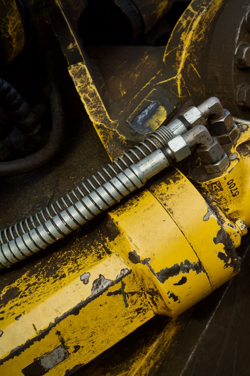
Hydraulic systems are the lifeblood of heavy equipment. From the lifting cylinders on an excavator to the steering system on a wheel loader, hydraulics power virtually every function that matters on the job site. Yet hydraulic system maintenance is one of the most overlooked aspects of equipment ownership — and one of the most costly when neglected.
This guide covers everything you need to know to keep your hydraulic systems running efficiently, prevent premature failures, and extend the life of one of the most expensive systems on your machine.
How Hydraulic Systems Work
Before diving into maintenance, it helps to understand the five core components of any hydraulic system and what each one does.
The Hydraulic Pump
The hydraulic pump is the heart of the system. It converts mechanical energy from the engine into hydraulic flow. Most heavy equipment uses variable-displacement piston pumps, which adjust flow output based on demand. Gear pumps are common on simpler systems and auxiliary circuits. The pump does not create pressure — it creates flow, and pressure builds when that flow meets resistance.
Control Valves
Hydraulic control valves direct fluid to the appropriate actuators based on operator input. Directional control valves (spools) open and close passages to cylinders and motors. Pressure relief valves protect the system from over-pressurization. Flow control valves manage speed. Modern machines use electrohydraulic controls where joystick signals command proportional solenoid valves electronically.
Cylinders and Motors
Hydraulic cylinders convert fluid pressure into linear force — pushing or pulling. Hydraulic motors convert fluid pressure into rotational force for swing drives, travel motors, and auxiliary functions. These actuators are generally robust but are susceptible to damage from contaminated fluid and worn seals.
The Reservoir
The hydraulic reservoir stores fluid, allows heat dissipation, permits air and contaminants to separate out, and provides a surge volume for demand spikes. Most reservoirs are vented or pressurized depending on the system design. The reservoir is also where you add makeup fluid — and where contamination most often enters if proper procedures aren’t followed.
Filters
Hydraulic filters are your primary defense against contamination-related failures. Most systems include a suction strainer (coarse), a return-line filter (primary filtration), and often a case-drain filter on piston pumps and motors. Filter ratings are expressed in microns; the lower the micron rating, the finer the filtration.
Hydraulic Fluid Types and Selection
Choosing the right hydraulic fluid is critical. The wrong fluid can destroy seals, reduce pump efficiency, and void your warranty.
ISO VG Grades
Hydraulic fluids are classified by ISO Viscosity Grade (VG), which describes the fluid’s viscosity at 40°C. Common grades for heavy equipment include:
- ISO VG 32 — Light-duty, cold-weather applications
- ISO VG 46 — General purpose, the most common grade for construction equipment
- ISO VG 68 — Higher-temperature or high-pressure applications
Always consult your OEM operator’s manual for the correct ISO VG specification. Mixing viscosity grades dilutes performance and can lead to improper film thickness in the pump.
Fluid Types
Beyond viscosity, hydraulic fluids differ by base stock and additive package:
- Mineral oil-based fluids — The standard for most heavy equipment; widely available and cost-effective
- Premium anti-wear (AW) hydraulic oils — Contain zinc-based (ZDDP) or ashless additive packages for improved pump wear protection
- High-viscosity index (HVI) fluids — Maintain stable viscosity across wider temperature ranges; excellent for variable climates
- Biodegradable hydraulic fluids — Vegetable ester or synthetic ester-based; required in environmentally sensitive work areas (near waterways, forests). Check OEM compatibility before switching.
Never mix fluids of different additive types without flushing the system. Incompatible additives can react, causing sludge, varnish deposits, and accelerated wear.
Hydraulic Fluid Sampling and Analysis
Fluid analysis is the single most powerful predictive maintenance tool available for hydraulic systems. A lab analysis costing $20–$40 per sample can prevent thousands of dollars in component failures.
What Fluid Analysis Detects
- Wear metals (iron, copper, aluminum, tin) — Indicate pump, valve, or cylinder wear
- Silicon — Suggests dirt ingestion or silicone sealant degradation
- Water contamination — Even small amounts of water cause corrosion and microbial growth
- Viscosity change — Indicates fluid degradation or contamination
- Acid number (TAN) — Measures oxidation and fluid life
How to Take a Proper Sample
Taking samples incorrectly produces misleading results. Follow these steps:
- Take samples when the system is at operating temperature (fluid fully circulated)
- Sample from a live zone — a sampling valve on the return line or pump case drain, not the reservoir drain port
- Use a clean sampling pump and tubing — never reuse tubing between samples
- Flush the sampling point with a small amount of fluid before drawing the sample
- Fill the sample bottle to the indicated fill line — no more, no less
- Label the sample with machine ID, component sampled, current hours, and hours since last oil change
Recommended sampling interval: every 250–500 hours or at each oil change.
Filter Change Intervals
Filters are consumables. Running them beyond their service life destroys the protection they provide.
Standard Intervals
| Filter Type | Typical Interval |
|---|---|
| Return-line filter | 500–1,000 hours (or per bypass indicator) |
| Case-drain filter | 500–1,000 hours |
| Suction strainer | Annual or at major fluid change |
| Breather/vent filter | 500 hours or annually |
Always change filters when changing fluid, regardless of hours. A new fluid charge pushed through a loaded filter immediately picks up contaminants.
Bypass Indicators
Most return-line filter housings have a bypass indicator — either a pop-up button or a differential pressure gauge. When the indicator trips, the filter element is loaded and must be changed immediately. Do not reset the indicator and continue operating.
Recommended product: The HYDAC filter condition indicator is a reliable visual indicator that mounts directly to filter housings and provides a clear go/no-go signal.
Contamination Prevention
Contamination causes an estimated 70–80% of all hydraulic system failures. The most common contamination sources are:
- Dirt entering through the reservoir breather
- Contaminated makeup fluid
- Ingress during maintenance (open ports, dirty funnels)
- Internal wear particles (self-generated contamination)
- Water from condensation or external leaks
Prevention Best Practices
- Use a high-quality breather filter rated at 3 microns or better. Replace it on schedule.
- Store bulk hydraulic fluid in a sealed, dedicated container with a desiccant breather — never in an open drum.
- Use clean, dedicated transfer equipment (pumps, hoses, funnels) for hydraulic fluid only. Color-code your equipment.
- Clean all fill ports and caps before opening. Even a small amount of grit entering the reservoir can cause catastrophic pump damage.
- Install quick-connect sampling valves on return lines and case drains to enable contamination-free sampling.
- When opening any hydraulic line or fitting, cap all open ports immediately with clean plastic caps. Keep a supply of assorted hydraulic port caps in your toolbox.
Recommended product: Minimess sampling valve kits allow clean fluid sampling without introducing contamination and are a low-cost upgrade for any serious maintenance program.
Common Failure Symptoms
Knowing the warning signs of hydraulic system distress allows you to intervene before a minor problem becomes a catastrophic failure.
Slow or Weak Cylinders
Slow or weak cylinder response is one of the most common complaints and can indicate:
- Low fluid level
- Worn pump (reduced flow output)
- Internal cylinder bypass (worn or damaged piston seals)
- Partially closed shutoff valve
- Clogged filter restricting flow
- Fluid viscosity too high for ambient temperature
Overheating
Hydraulic fluid operating above 180°F (82°C) degrades rapidly. Consistent overheating causes varnish deposits, seal deterioration, and accelerated pump wear. Common causes include:
- Dirty or clogged oil cooler
- Faulty cooler bypass thermostat
- Continuous high-load operation without duty cycle relief
- Fluid level too low (insufficient volume to dissipate heat)
- Wrong fluid viscosity (too light at operating temperature)
Unusual Noise
- Cavitation (screaming or whining) — Pump is not receiving adequate suction; check fluid level, suction strainer, and fluid temperature
- Aeration (banging or knocking) — Air is entering the system; check for low fluid, loose suction line fittings, or foaming fluid
- High-pitched squealing — Often indicates a relief valve chattering or a pump in early stages of wear
Hose Inspection and Replacement
Hydraulic hoses are high-pressure safety items. A hose failure under pressure is not just an equipment problem — it’s a serious personnel hazard.
Inspection Checklist
Inspect hoses daily during pre-operation checks:
- Cuts, abrasions, or chafing on the outer cover
- Bulging or blistering (indicates internal liner failure)
- Kinked sections (kinks restrict flow and cause fatigue cracking)
- Fittings for corrosion, cracks, or weeping fluid
- Missing clamps or hose guards at contact points
Replacement Guidelines
- Replace any hose showing visible damage immediately
- Replace hoses on a preventive schedule every 4–6 years regardless of condition, per SAE J1273 guidelines
- Always replace with hoses rated to the same or higher working pressure and temperature
- Never repair a high-pressure hydraulic hose with tape or sealant — replace it
Recommended product: Keep a supply of Parker or Gates hydraulic hose assemblies appropriate for your machine’s most commonly replaced runs. Pre-made assemblies save downtime.
Seal Replacement Indicators
Cylinder seals and pump shaft seals are wear items. Watch for these signs:
- External fluid leakage at cylinder rod — rod seal worn
- Cylinder drift under load without operator input — piston seal bypass
- Fluid leakage at pump shaft — shaft seal worn; also check for excessive case pressure driving seal failure
- Contaminated fluid with rubber particles — seal material degrading internally
When replacing cylinder seals, always install a complete seal kit for that cylinder. Never replace only the rod seal if the piston seal is accessible. Use the correct seal compound (nitrile, polyurethane, or PTFE) as specified for the fluid type.
Flushing Procedures
A system flush is required after a major component failure (pump, motor, or cylinder) that introduced wear debris, after a fluid contamination event, or when converting to a different fluid type.
Basic Flush Procedure
- Drain all fluid from the reservoir, filter housings, and accessible lines
- Replace all filter elements
- Fill with a flushing fluid (low-viscosity mineral oil or the new operating fluid)
- Run the system at low pressure and moderate temperature for 30–60 minutes, cycling all functions
- Drain completely while hot
- Replace filter elements again
- Fill with clean operating fluid and take an initial sample for baseline analysis
For severe contamination events, a professional high-velocity flush using dedicated flushing equipment may be required before returning the machine to service.
Hydraulic System Maintenance Schedule
Use this schedule as a baseline. Always defer to your OEM service manual for machine-specific intervals.
Daily (Pre-Operation)
- Check fluid level in reservoir
- Inspect all visible hoses for damage or leaks
- Check for external leaks at cylinders, pumps, and fittings
- Check for abnormal noises during operation
Every 250 Hours
- Inspect breather/vent filter; replace if dirty
- Take fluid sample for analysis
- Check all hose clamps and mounting hardware
Every 500 Hours
- Change return-line filter element
- Change case-drain filter element
- Inspect suction strainer (clean or replace as needed)
- Review fluid analysis results; change fluid if indicated
Every 1,000–2,000 Hours (or Annually)
- Complete fluid change (interval per OEM spec and fluid analysis)
- Inspect all cylinder rod surfaces for scoring or corrosion
- Inspect pump mounting and coupling
- Pressure-test relief valve settings
Every 4–6 Years
- Replace all hydraulic hoses regardless of apparent condition
2026 decision refresh
Quick decision: protect hydraulic systems by controlling contamination, temperature, fluid compatibility, and stored energy. Most expensive failures start as small maintenance misses: dirty fill practices, ignored filter indicators, overheated oil, wrong fluid, or damaged hoses left in service.
| Maintenance check | Good practice | Stop-work trigger |
|---|---|---|
| Fluid level and condition | Check at the specified temperature and position | Milky, burnt, foamy, or metal-contaminated oil |
| Filters and breathers | Change by interval or restriction indicator | Bypass indicator tripped or unknown service history |
| Hoses and fittings | Inspect for abrasion, blistering, leaks, and routing | Pinholes, exposed reinforcement, or active leaks |
| Cylinders | Check rod scoring and seal leakage | Damaged rod chrome or uncontrolled drift |
| Service work | Relieve pressure and follow lockout procedures | Any unexpected movement or trapped pressure concern |
Safety source note: OSHA lockout/tagout guidance covers servicing and maintenance where unexpected startup or stored energy could injure workers. Hydraulic pressure can inject fluid through skin; suspected injection injuries require emergency medical care.
Related tool and guides
- Heavy equipment inspection log - record daily hydraulic, hose, and fluid checks.
- Heavy equipment fluids guide - match hydraulic oil to OEM requirements.
- Oil analysis for heavy equipment - use sampling to catch wear before failure.
- Excavator maintenance schedule - apply intervals to a common hydraulic-heavy machine.
Final Thoughts
Hydraulic system maintenance is not optional — it’s what separates equipment that runs for 15,000+ hours from machines that spend weeks in the shop at 5,000. The good news is that a disciplined maintenance program is straightforward and relatively inexpensive compared to the cost of a single pump or motor replacement.
Invest in quality filtration, use the right fluid, keep contamination out, and sample your oil regularly. Your hydraulic system will reward you with reliable performance and a dramatically lower total cost of ownership.
Connect maintenance work to ownership cost
These resources help turn hydraulic maintenance needs into realistic ownership, financing, transport, and inspection assumptions.
- Equipment ownership cost calculator
Include maintenance reserves, repairs, downtime, and utilization in equipment decisions.
- New vs. used heavy equipment
Use maintenance condition as a key part of used-equipment evaluation.
- Heavy equipment financing options
Check whether cash flow can absorb repairs beyond the payment.
- Equipment transport guide
Add mobilization and transport constraints to the ownership model.

Ironworks Insider Editorial Team
Independent trade-focused editorial team