Telehandler load chart explained: A pre-lift guide
Quick answer
A telehandler load chart is valid only for the machine, attachment, forks, tires, stabilizer position, and load-center conditions identified on it. Confirm the load weight, load center, target height and forward reach, then locate the entire planned path inside an allowed capacity zone. If a point is on a zone boundary, use the lower capacity. Stop if any required input, approval, or chart is missing.
How to complete a telehandler pre-lift chart check
Record the inputs needed to decide whether a planned load position is within the exact machine-and-attachment chart.
1. Match the equipment and chart
Verify the machine model and serial applicability, attachment, carriage, forks, tires, stabilizer position, and every configuration note against the chart and operator manual.
2. Verify the load
Document the load weight from a reliable source and locate its center of gravity and load center as the manufacturer defines them.
3. Measure the placement point
Record the required vertical height and horizontal reach from the reference points printed on the chart.
4. Find the governing zone
Plot the required point, confirm the planned path remains inside the operating envelope, and use the lower capacity at any boundary.
5. Check every component limit
Compare the chart capacity with the machine, attachment, carriage, and fork ratings; the lowest applicable rating controls.
6. Confirm site conditions
Verify the chart assumptions and manual limits for ground support, level, tires, wind, visibility, and stabilizers.
7. Stop on any unknown
Do not lift until every unknown, mismatch, illegible marking, unapproved attachment, unstable surface, or out-of-zone point is resolved.
Common questions
- What does a telehandler load chart show?
- It shows the permitted operating envelope and capacity zones for a specified machine, attachment, load center, and configuration at different lift heights, forward reaches, boom angles, and extension positions.
- Can I use a load chart from the same telehandler model?
- Only if the chart identification and every required configuration detail match the actual machine and attachment. A similar-looking or downloaded chart cannot authorize a lift when that match is unverified.
- Which capacity applies on a line between two zones?
- Use the lower of the two capacities. Also compare the chart value with the ratings of the forks, attachment, carriage, and machine; the lowest applicable limit controls.
- Does this guide replace telehandler operator training?
- No. It is a planning aid. OSHA requires training and workplace evaluation, and the exact cab chart, operator manual, employer procedures, and site plan control the lift.
Source note: Reviewed October 2026 against JLG load-chart and attachment guidance, the current official Genie GTH-1056 operator manual (Part No. 1311461GT), and OSHA powered-industrial-truck rules. This guide does not replace operator training, the cab chart, the exact machine manual, employer evaluation, or a site-specific lift plan.
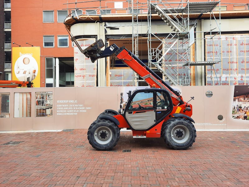
A telehandler load chart is a permission map for one machine-and-attachment configuration—not a promise that the machine can carry its headline capacity anywhere. To use it, verify the exact chart, load weight and center, placement height, forward reach, boom position, and site conditions. Then confirm the whole planned lift stays within an allowed capacity zone.
If any input is unknown, the answer is not “close enough.” Stop the lift. This article helps a trained operator and lift planner organize the required information; it cannot authorize a real lift or replace the chart in the cab.
What a telehandler load chart tells you
Most telehandler charts combine several pieces of information:
- Vertical height, usually measured from the supporting surface
- Forward reach, often measured from the front face of the front tire
- Capacity zones, showing the maximum load allowed in each part of the operating envelope
- Boom angle lines and extension letters or marks, which connect the diagram to indicators on the machine
- Configuration notes, including the approved attachment, carriage, forks, stabilizer position, tires, and assumed load center
JLG’s load-capacity-chart guide explains that the grid relates height and reach to the machine’s operating envelope, while boom angle and extension markings help the operator stay within the selected zone.
That is different from a crane chart, which may organize ratings around operating radius, boom length, counterweight, and outrigger setup. Use our crane load chart guide only for crane-specific concepts—not as a substitute for a telehandler chart.
Start by matching the exact chart
Before reading a capacity number, compare the chart header and notes with the equipment in front of you. Record:
| Match item | What to verify |
|---|---|
| Machine | Make, model, and serial-number applicability |
| Attachment | Type, model, weight, dimensions, and approval status |
| Load handling parts | Carriage, fork type, fork length, fork rating, and fork position |
| Setup | Stabilizers up or down, frame-level requirements, and approved tire specification |
| Chart basis | Units, stated load center, and every note or restriction |
The current official Genie GTH-1056 operator’s manual, Part No. 1311461GT, for example, contains different charts for different carriages, fork arrangements, attachments, and stabilizer positions. That is why a chart copied from another GTH-1056—or a standard-carriage chart used with a truss boom—does not establish capacity for the actual setup.
JLG’s approved-attachment guidance says the attachment details and telehandler model must match the capacity chart. It also directs users not to use an attachment when the approval conditions are not met. “It fits the coupler” is not an approval method.
Verify the load weight and load center
Get load weight from a reliable source such as a supplier document, marked package, engineered takeoff, or approved weighing method. Include everything the applicable chart and manual require, which may include the attachment, fork-mounted device, rigging, or other load-handling components.
Next, locate the center of gravity and determine the load center using the definition and reference point in the exact manual. A long, uneven, or off-center load can move its center of gravity farther from the fork face and reduce usable capacity.
Many fork-carriage charts use a 24-inch horizontal load center, but that is not permission to assume every chart does. JLG publishes an equivalent-load method for certain applications beyond 24 inches. Use such a calculation only when the exact manufacturer documentation authorizes it and provides the procedure. Otherwise, contact the manufacturer or dealer for the correct chart and direction.
Measure height and forward reach
Measure the placement point using the same origins shown on the chart:
- Record the vertical height to the load’s intended position.
- Record the horizontal reach from the chart’s stated machine reference point to the load center at placement.
- Check the approach, placement, and withdrawal path—not just the final point.
Do not estimate from floor levels or count boom sections from a distance. Obstructions may require more reach than the straight-line plan suggests, and settling or repositioning can change the geometry.
Find the capacity zone and use the lower-bound rule
Plot the required height and reach on the exact chart. The intersection must be inside the operating envelope and within a capacity zone that supports the verified load. Then note the boom-angle and extension limits associated with that zone.
If the point falls on a boundary between two capacity zones, use the lower capacity. JLG gives this instruction in its telehandler stability and chart-reading guidance.
The governing capacity is also the lowest applicable limit among the proper chart, attachment identification plate, forks, carriage, and machine rating. A higher number elsewhere does not override the lowest one.
Illustrative example only
Suppose a training diagram shows a verified load point on the line between a 5,000-pound zone and a 4,000-pound zone. For that exercise, the operator uses 4,000 pounds, then checks the boom angle and extension limits for that lower zone.
This example cannot authorize a lift. Its numbers are not tied to a real machine, attachment, chart, load center, or site. Use only the legible chart supplied for the actual configuration.
Confirm configuration and ground conditions
A chart value depends on its stated assumptions. Before lifting, confirm the operator manual and lift plan requirements for:
- Firm, stable ground with adequate support
- Machine level and permitted frame-level or stabilizer setup
- Correct tires, pressure, and condition
- Load centered and supported as required on the forks
- Wind and environmental limits
- Visibility, overhead hazards, exclusion zones, and pedestrian control
- A serviceable machine with a completed inspection
Use the ground conditions and equipment stability guide to organize surface observations, and record machine defects with the heavy-equipment pre-operation inspection. Neither page changes an OEM limit.
Telehandler pre-lift worksheet
Complete this record before the load moves. Blank or conflicting fields are stop signals.
| Required input | Recorded value | Verified from |
|---|---|---|
| Machine model / serial applicability | Data plate and manual | |
| Attachment / carriage / forks | IDs, ratings, and approval documentation | |
| Correct chart present and legible | Cab chart identifier | |
| Stabilizer and machine configuration | Chart and manual | |
| Load weight | Supplier or approved source | |
| Load center / center of gravity | Load data and manufacturer method | |
| Target height | Site measurement | |
| Maximum forward reach | Site measurement | |
| Governing capacity zone | Exact chart | |
| Boom angle / extension limits | Exact chart | |
| Ground, level, tires, and weather | Site and equipment checks | |
| Lift path and exclusion controls | Site-specific lift plan |
After the worksheet is complete, a trained and authorized person still needs to apply the employer’s procedures and exact manual. For the wider machine-selection question, see the telehandler buying guide. For training responsibilities, start with the forklift certification guide.
Stop conditions: do not make the lift
Stop and resolve the issue when:
- The load weight or load center is unknown
- The chart is missing, illegible, damaged, or does not match the machine and attachment
- The attachment is unapproved or its rating cannot be verified
- A required configuration, tire, stabilizer, fork, or carriage detail differs from the chart
- The placement point or any part of the planned path is outside the allowed envelope
- The load exceeds the lower applicable capacity at a zone boundary
- Ground support, level, load stability, visibility, or weather falls outside the plan or manual limits
- The machine has an unresolved inspection defect or warning
OSHA 1926.602 requires rated capacity to be posted and not exceeded on construction lift trucks, and requires manufacturer approval for changes affecting capacity or safe operation. Its training rule points to the requirements in OSHA 1910.178(l), including instruction on attachments, capacity, stability, surface conditions, and operating limitations, plus practical training and workplace evaluation.
The decision in one sentence
Proceed only when the exact chart matches the complete configuration, every input is verified, the entire planned path remains in an allowed zone, and the load is below the lowest applicable limit. Otherwise, lower the load, choose a different approved setup or machine, or obtain manufacturer and site-plan direction before continuing.

Ironworks Insider Editorial Team
Independent trade-focused editorial team